
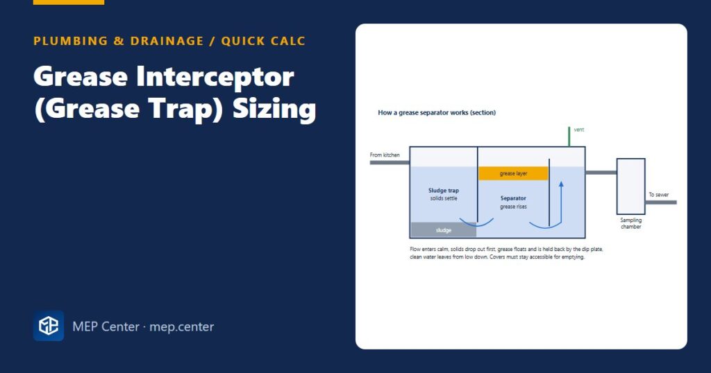
Fat that leaves a commercial kitchen warm and liquid sets hard a few metres down the drain. A grease interceptor that is too small lets it through and blocks the sewer; one that is undersized for hot dishwasher water simply washes the trapped grease out again. Sizing is quick once you know what each method is really asking for.
EN 1825-2: the nominal size method
NS = Qs × ft × fd × fr
- Qs — maximum waste water flow to the separator, L/s. Found either from the connected fixtures (their discharge flows with a simultaneity factor) or from the number of meals per day and the kitchen’s working hours.
- ft — temperature factor: 1.0 when inflow stays at or below 60 °C, 1.3 when hotter water (dishwashers, combi-steamers) reaches the separator.
- fd — density factor: 1.0 for ordinary kitchen fats (density up to 0.94 g/cm³), 1.5 for denser oils that separate more slowly.
- fr — detergent factor: 1.3 where detergents or rinsing agents are used, which is nearly every commercial kitchen; higher in special cases.
Round NS up to the next size offered by manufacturers (2, 4, 7, 10, 15, 20 and so on). The upstream sludge trap is sized with it: its volume is a multiple of NS (at least about 100 L per NS for a normal kitchen, more where a lot of sludge is expected, such as with peeling machines or meat processing).
Worked example (EN 1825-2)
Kitchen: restaurant with two pot sinks, a prep sink, a hood-type dishwasher and floor gullies. From the fixture discharge flows and simultaneity: Qs = 2.0 L/s.
- Dishwasher discharge is above 60 °C → ft = 1.3.
- Ordinary cooking fats → fd = 1.0.
- Detergents used → fr = 1.3.
- NS = 2.0 × 1.3 × 1.0 × 1.3 = 3.38 → select NS 4.
- Sludge trap at 100 L per NS → at least 400 L.
Sanity check: without the temperature and detergent factors you would have chosen NS 2 — half the size. Those two factors are where most undersized separators come from.
US practice: flow rate from the sink volume
For hydromechanical interceptors the common method takes the volume of the sinks, assumes they are about 75 % full when the plug is pulled, and divides by the drain-down time (1 minute, or 2 minutes for a slower drain):
Two-compartment pot sink, each bowl 600 × 600 × 350 mm = 126 L → 252 L. At 75 % full: 189 L.
1-minute drain: 189 ÷ 60 ≈ 3.2 L/s (≈ 50 gpm). 2-minute drain: ≈ 1.6 L/s (≈ 25 gpm).
Select an interceptor rated at or above that flow and check the grease storage capacity against the cleaning interval.
Large gravity interceptors under IPC/UPC are sized from drainage fixture units or from a volume formula, and many water authorities publish their own rules. Always check the local authority first — it often overrides the model code.
Method comparison
| EN 1825-2 | US practice (IPC/UPC + authority) | |
|---|---|---|
| Basic input | Peak waste water flow, L/s | Sink volume and drain time, or fixture units |
| Corrections | Temperature, density, detergent factors | Usually none; storage and cleaning interval checked |
| Result | Nominal size NS + sludge trap volume | Rated flow (gpm) or tank volume (gal) |
| Downstream | Sampling chamber | Sampling port / manhole as required |
Typical values — verify with the edition adopted locally.
Layout rules that matter as much as size
- Connect only kitchen waste. WCs, urinals and rainwater must never go through a grease separator.
- Keep the separator close to the kitchen so fat stays liquid, but where a tanker can reach it for emptying.
- Vent the inlet and outlet pipework and the separator as the standard and code require.
- Most codes restrict food waste disposers upstream of an interceptor — check before allowing them.
- Lay the incoming pipe at a steady fall; read the slope rules in drainage pipe sizing with EN 12056 and IPC, and the venting basics in plumbing vent pipe rules.
Ready-made drawings and tools for your next project
CAD block libraries, detail drawings and AutoCAD tools made by practising MEP engineers.
FAQ
What is the EN 1825-2 formula for grease separators?
NS = Qs × ft × fd × fr, where Qs is the peak waste water flow in L/s and the factors account for water temperature, grease density and the use of detergents. Round up to the next manufacturer size.
Why does dishwasher water make the separator bigger?
Hot water above about 60 °C keeps fat liquid and emulsified, so it separates poorly. EN 1825-2 applies a temperature factor of 1.3, which increases the nominal size.
Can toilets or rainwater drain through a grease trap?
No. Only kitchen waste should enter a grease separator; sanitary waste and rainwater must bypass it and connect downstream.